4. Encoder interfaces: Absolute electrical interfaces
4.1 Parallel
4.2 Analog
4.3 BiLL
4.4 Serial point-to-point
4.5 EnDat 2.1
4.6 EnDat 2.2
4.7 SSI
4.1 Parallel
Parallel output provides an absolute position available simultaneously on the output. It may be provided as binary or transformed in gray code format. Gray code means a single-bit change between each position step, which can reduce transmission errors.
Parallel output encoders can also accept inputs, for example setting the counting direction.
The advantage of parallel output is that it is fast and all the data is available in real time, all the time.
4.2 Analog
The absolute position can also be represented as an analog current output. 0-20 mA or 4-20 mA for a full-scale output.
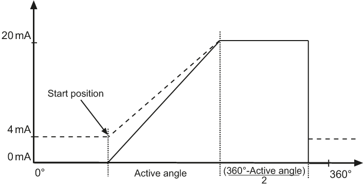
Image text: Output signal analog interface.
On special request an analogue output with a teach-in functionality can also be offered. The teach-in function implies that the encoders active angle can be configured at will. A maximal full-scale output 0 or 4-20 mA current value can therefore be distributed over the total measuring range.
4.3 BiLL (RS485 based)
![]()
BiLL is a bi-directional master/slave communication used on absolute encoders. The protocol can be used for RS485 transmission standards or for a multi-drop bus system using the RS485 standard. Data are sent in hexadecimal format and the addressed encoder answers only on a master request. The protocol includes position data in binary format, a checksum for transmission reliability, a hold command, a change of baud rate command and an error message.
4.4 Serial point-to-point
Serial transmission means that bit information is transmitted sequentially in the same pair of conductors rather than sending each bit in its own conductor as in parallel transmission.
One of the advantages of serial transmission is that installation costs less; fewer wires means less work and less documentation.
There are several more or less standardized methods for serial transmission of data, all with their advantages and disadvantages. The following is a short description of the most common serial standards used for communication with encoders.
4.5 EnDat 2.1

The EnDat 2.1 interface is a digital, bidirectional interface for encoders. It is capable of transmitting position values from absolute encoders, as well as reading and updating information stored in the encoder.
Thanks to the serial transmission method, only four signal lines are required. The absolute position data are transmitted in synchrony with the clock signal generated by the subsequent electronics. The type of transmission (position values, parameters, diagnostics, etc.) is selected by mode commands that the subsequent electronics send to the encoder.
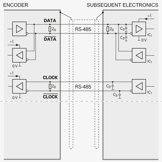
Image text: Recommended subsequent electronics.
A clock pulse (CLOCK) is transmitted by the subsequent electronics to synchronize data transmission. When not transmitting, the clock signal defaults to HIGH.
One data packet is sent in synchrony per data transmission. The transmission cycle begins with the first falling clock edge. The measured values are saved and the position value calculated. After two clock pulses (2T), the subsequent electronics transmit the mode command “Encoder transmit position value”. After successful calculation of the absolute position value (tcal - see table), the start bit begins the data transmission from the encoder to the subsequent electronics.
|
Interface |
Endat 2.1 |
|
Clock frequency fc |
100 kHz ... 2 MHz |
|
Calculation time for Position value tcal |
< 5 µs |
|
Recovery time tm tr |
10 to 30 µs Max. 500 ns |
The encoder then transmits the absolute position value, beginning with the LSB. Its length varies depending on which encoder is being used. The number of required clock pulses for transmission of a position value is saved in the parameters of the encoder manufacturer. The data transmission of the position value is completed with the Cyclic Redundancy Check (CRC).
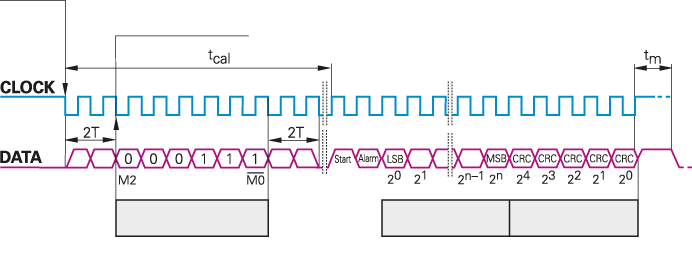
Image text: Data transfer EnDat 2.1.
EnDat 2.1 encoders are available with incremental 1Vpp signals.
Note: Every Leine & Linde gateway for fieldbus communications communicates with the encoder via the EnDat 2.1 interface.
4.6 EnDat 2.2
With EnDat 2.2 it is possible to transfer additional data with the position value without sending a separate request for it. EnDat 2.2 is compatible with EnDat 2.1.
The extended EnDat interface version 2.2 is compatible in its communication, command set and time conditions with the previous version 2.1, but also offers significant advantages. It makes it possible, for example, to transfer what is termed “additional data” with the position value without sending a separate request for it. The interface protocol was expanded and the time conditions were optimized as follows:
- Increased clock frequency (CLOCK) 16 MHz
- Optimized calculating time, position value acquisition within 5 μs
- Minimized dead time (recovery time) 1.25 to 3.75 μs
- Expanded power supply range, UP = 3.6 to 5.25 V or 3.6 to 14 V at encoder
|
|
Without |
With |
|
Clock frequency fc |
100 kHz ... |
100 kHz ... 16 MHz |
|
Calculation time for Position value tcalf Parameter tac |
Typical of EnDat 2.2 encoders: < 5 µs
Max. 12 ms |
|
|
Recovery time tm
tR tST |
EnDat 2.1: 10 to 30 µs EnDat 2.2: 10 to 30 µs or 1.25 to 3.75 us (fc > 1 MHz) (parameterizable)
Max. 500 ns – 2 µs to 10 µs |
|
|
Data delay time tD |
(0.2 + 0.01 x cable length in m) µs |
|
|
Pulse width tHI tLO |
0.2 to 10 µs 0.2 to 50 ms to 30 µs (with LC) |
Pulse width fluctuation HIGH to LOW max. 10 % |
EnDat 2.2 encoders from Leine Linde are available with incremental 1 Vpp signals.
4.7 SSI
SSI or Synchronous Serial Interface, is a digital point-to-point interface. It provides unidirectional communication at speeds up to 1.0 MHz by the use of only 4 wires.
The absolute position value, beginning with the most significant bit, is transferred over the data lines (DATA) in synchrony with a CLOCK signal from the control. The SSI standard data word length for singleturn absolute encoders is 13 bits, and for multi-turn absolute encoders 25 bits. The position value is transmitted in gray or binary code format.
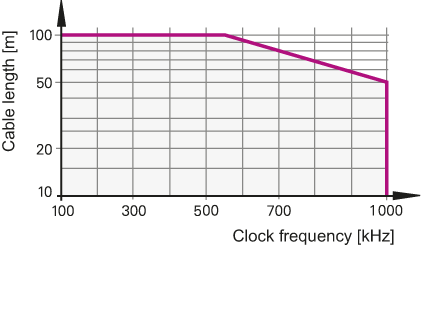
Image text: Permissible cable length SSI.
In the quiescent state the clock and data lines are on high level. The current position value is stored on the first falling edge of the clock. The stored data is then clocked out on the first rising edge.
After transmission of a complete data word, the data line remains low for a period of time (t2) until the encoder is ready for interrogation of a new value. If another data output request (CLOCK) is received within this time, the same data will be output once again. If the data output is interrupted (CLOCK = high for t > t2), a new position value will be stored on the next falling edge of the clock, and on the subsequent rising edge clocked out to the subsequent electronics.
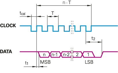
Image text: Data transfer SSI.
|
Interface |
SSI |
|
Clock frequency T |
1 ... 10 µs |
|
Calculation time for Position value tcal |
< 5 µs |
|
Recovery time t1 t2 n |
0.4 µs 12 ... 30 µs 13 ... 25 bit |
For the 600 series encoders, the following functions can be activated via the programming inputs of the interfaces by applying the input to a logic high level, i.e +EV:
Direction of rotation
Continuous application of a HIGH level reverses the direction of rotation for ascending position values.
Zero setting (setting position to zero)
Applying a positive edge (tmin > 1 μs) sets the current position to zero.
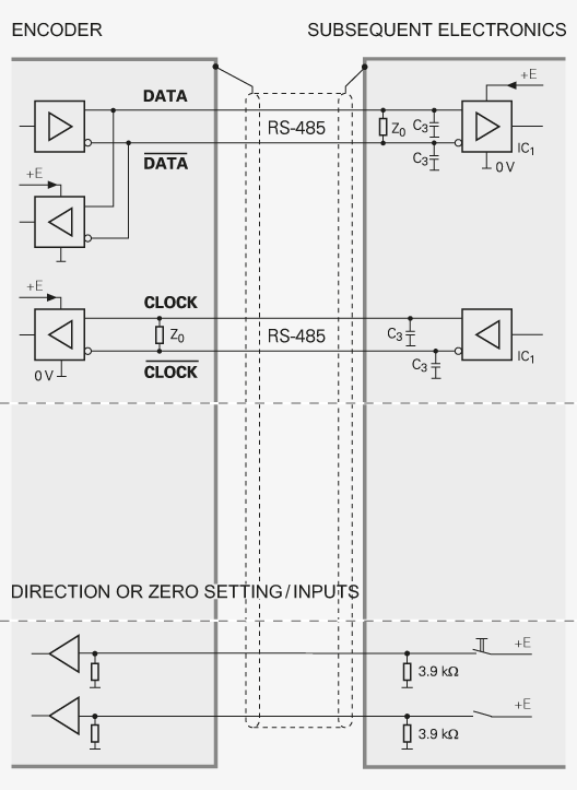
Image text: Recommended subsequent electronics.
Note: The programming inputs must always be terminated with a resistor (see input circuitry of the subsequent electronics).
The SSI interface is also available in combination with incremental 1 Vpp, HTL or RS422 signals on certain models.
Example of absolute encoders
Here you can see some examples of our most beloved absolute encoders.