5. Encoder interfaces: Fieldbus interfaces and communication protocols
5.1 PROFIBUS DP
5.2 PROFINET IO
5.3 CANopen
5.4 DeviceNet
5.5 DRIVE-CLiQ
5.1 PROFIBUS DP
PROFIBUS is a powerful and versatile 2-wire non-proprietary open fieldbus standard defined by several international standards such as EN 50170, IEC 61158 together with different device profiles.
The encoder device profiles for PROFIBUS-DPV0, DPV1 and DPV2 define the functionality of encoders connected to a PROFIBUS-DP bus. There are two encoder profiles available 3.062 and 3.162 defining the functionality of encoder for the different versions of PROFIBUS DP.
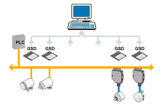
Image text: Network and configuration of PROFIBUS
Encoder Profile for DPV0, profile number 3.062
The operating functions in this profile are divided into two device classes. Class 1 encoders offer basic functions that all PROFIBUS-DP encoders must support. An encoder of class 1 can optionally support selected functions of class 2 but these functions must be implemented according to the profile.
Encoders of class 2 must support all functions of class 1 as well as the additional functionality of class 2.
Encoder Profile for DPV1 and DPV2, profile number 3.162
In addition to the functionality enabled in DPV0 and acyclic data exchange, expansions to the PROFIBUS were required to enable the interface in time-critical applications. As a result, DP-V2 functionality such as slave-to-slave communication and isosynchronous data exchange was added.
Slave-to-slave communication means, as the name implies, that slaves in a net can exchange information with each other via broadcast messages without communication being initiated by the master. This type of communication is very efficient and fast, which reduces the response time on the bus by up to 90%.
Isosynchronous data exchange implies that the master can reach several slaves simultaneously with for example set point values, or receives feedback values from different slaves. With the isosynchronous mode, a system can be set up where all slaves set their output values and read their input values at the same time with a very high accuracy. This functionally results in synchronization between many different slaves within 1 μs.
For further information regarding the Encoder functionality refer to the device profiles. These profiles and PROFIBUS technical information can be ordered at PNO in Karlsruhe, Germany (www.PROFIBUS.com).
To choose between the different profile versions, different GSD files are available. The user can select the version that fits their hardware and software.
Encoder functionality
The encoder can be configured as a class 1, 2 (DPV0) or class 3 or 4 (DPV2) PROFIBUS slave device. Class 2 configuration is extended to optionally access speed information from the encoder.
In the basic class 1 or 3 configuration only output values/positions are available.
The following functions can be performed or programmed:
- Position read out
- Changed direction of counting
- Diagnostic data up to octet 16
The following functions are available in addition on the class 2 or 4 functions:
- Scaling function
- Preset Value Function
- Speed read-out (class 2)
- Extended diagnostic data
5.2 PROFINET IO
ROFINET is an open standard for industrial Ethernet and uses TCP/IP and IT standards. This fieldbus interface satisfies all requirements for automation technology and it is widely used within factory automation and process automation. PROFINET IO describes an I/O data view of distributed I/O. It includes real-time (RT) communication and isochronous real-time (IRT) communication for cyclic process data. PROFINET is standardized in IEC 61158 and IEC 61784.
Leine & Linde PROFINET encoders conform to the encoder profile v4.1 (3.162) for PROFIBUS and PROFINET. The encoder profile version 4.1 is a further development of the encoder profile for DPV2 encoders’ version 3.1. It includes all the encoder functionality from encoder profile version 3.1 but it has been expanded with the usage of encoders with PROFINET and additionally the definition of a 64 bit position value.
Application class definition:
Class 3
Encoder with base-mode parameter access and limited parameterization of the encoder functionality. Isochronous mode is not supported.
Class 4
Encoder with scaling, preset, code sequence and base mode parameter access. Isochronous mode (IRT) is supported.
5.3 CANopen
The CANopen communication profile is based on the CAN Application Layer (CAL) specification from the CiA (CAN in Automation). CANopen is regarded as a robust fieldbus with highly flexible configuration possibilities. It is used in many various applications all based on different application profiles.
CANopen comprises a concept to configure and communicate real-time data using both synchronous and asynchronous messages. Four types of messages (objects) are distinguished:
- Administrative messages (Layer Management, Network Management, etc.)
- Service Data Messages (SDO)
- Process Data Messages (PDO)
- Pre-defined Messages (Synchronization-, Timestamp-, Emergency Messages)
For further information please view the CANopen specification available at www.can-cia.org.
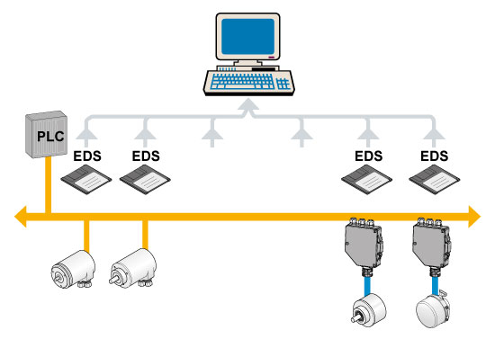
Image text:Network and configuration of CAN
The Encoder Profile defines the functionality of encoders connected to CANopen. The operating functions are divided into two device classes:
Class 1
The Mandatory class with a basic range of functions that all encoders must support. The class 1 encoder can optionally support selected class 2 functions, these functions must however be implemented according to the profile.
Class 2
Where the encoder must support all class 1 functions and all functions defined in class 2. The full class 2 functionality includes:
- Absolute position value transfer using either polled, cyclic or sync mode
- Speed and acceleration output values
- Change of code sequence
- Preset value settings
- Scaling of the encoder resolution
Advanced diagnostics including:
- Encoder identification
- Operating status
- Operating time
- Alarms and warnings
All programming and diagnostic parameters are accessible through SDO’s. The output position value from the encoder is presented in a binary format.
5.4 DeviceNet
DeviceNet is a low-level network that provides connections between simple industrial devices (sensors, actuators) and higher-level devices (controllers). DeviceNet provides Master/Slave and Peer-to-Peer capabilities over the CAN bus.
DeviceNet has two primary purposes:
- Transport of control-oriented information associated with low-level devices
- Transport of other information, which is indirectly related to the system being controlled, such as configuration parameters
A DeviceNet node is modelled as a collection of Objects. An Object provides an abstract representation of a particular component within a product. The realization of this abstract object model within a product is implementation-dependent. In other words, a product internally maps this object model in a fashion specific to its implementation.
Like all other fieldbus interfaces, there is also an Encoder Profile which defines the functionality of encoders connected to a DeviceNet network. In the Encoder Profile are all Objects described that are used from DeviceNet Object library. Particular interesting is the Position Sensor Object (0x23 Hex). It describes the services that are available for fetching positions, scaling of position values and other useful information.
The full profile describes the encoder functionality which includes:
- Absolute position value transfer
- Speed output values
- Change of code sequence
- Preset value settings
- Scaling of the encoder resolution
Advanced diagnostics including:
- Encoder identification
- Operating status
- Operating time
- Alarms and warnings
5.5 DRIVE-CLiQ
DRIVE-CLiQ is an Ethernet-based communication protocol from Siemens for connection of sensors. This interface is specially made for drive applications for an easy connection between components such as converters, motors and sensors. With a speed of 100 Mbit/s and a cycle time of 31.25 µs, DRIVE-CLiQ has the performance required for the most demanding applications. Components with DRIVE-CLiQ can be automatic configured with each other since every component has an electronic label to store component-specific data used during commissioning drive systems. Another characteristic with the protocol is that the cabling onsite is reduced. Up to five units may be connected to a hub for transfer of data over a common cable. The Drive-CLiQ encoders are designed for transfer of both speed and position and are supplied with specially adapted connectors, with power supply and data in the same connector making it easy to connect the encoders.
Example of absolute encoders
Here you can see some examples of our most beloved absolute encoders.