2. How incremental encoders work
2.1 Incremental encoders measuring principle
2.2 Resolution, line count and pulse rate
2.3 Measuring steps
2.4 Accuracy
2.5 Channel separation on incremental encoders
2.1 Incremental encoders measuring principle
With the incremental measuring principle, the graduation consists of a periodic grating structure producing a defined number of sinusodial signals when the encoder shaft is rotated. These sinusodial signals can be converted into other signal formats and used in two different ways. Either for relative positioning or more commonly as speed feedback devices. Relative position information can be obtained by counting the individual increments (measuring steps) from some point of origin. When such a semi-absolute reference is required to ascertain positions, the graduated discs are provided with an additional track that bears a reference mark.

Image text: Incremental graduated code disc.
The rotational speed of the encoder shaft can be determined by calculating the frequency of the sinus-odial signals. Incremental encoders are normally used in closed loop, speed control loops or as speed feedback devices.
2.2 Resolution, line count and pulse rate
The resolution, line count or pulse rate are just different designations of the number of signal periods per channel and per revolution of an incremental encoder. Denominations of these signals vary between encoder manufacturers but Leine Linde commonly use S00, S90 and Sref. The signals S00 and S90 are 90 el° displaced from each other. S00 appear 90 el° before S90 when the encoder shaft is turned clockwise. A, B and N or K1, K2 and K0 are other examples of denominations used on incremental signals.

Image text: Output signals from an incremental encoder.
For absolute encoders, resolution is stated as the number of bits. The number of bits (or unique positions per revolution) is calculated as 2n where n equals the number of bits. The total resolution of multiturn encoders also includes the number of distinguishable revolutions.
2.3 Measuring steps
In order to obtain higher resolutions from an incremental encoder, evaluation of all raising and falling pulse edges may be monitored. This is normally done by subsequent electronics as a quadruple, double or single evaluation. A measuring step is the definition of maximal number of edges as acquired when the subsequent electronics support quadruple evaluation, i.e. maximal measuring steps = 4 x line count. The example below indicates what different measuring step evaluation results in as seen by the subsequent electronics. In the example a 1024 ppr line count disc is used.
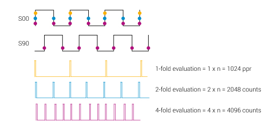
Image text: Measuring steps.
2.4 Accuracy
The accuracy of measurements with encoders is mainly determined by:
- Directional deviation of the radial grating
- Eccentricity of the graduated disc to the bearing
- Radial deviation of the bearing
- Error resulting from the mechanical installation
- Interpolation error during signal processing in the integrated or external interpolation and digitizing electronics
When speaking about accuracy of incremental encoders, the unit el° (electrical degrees) is normally used. For one signal period of the output signal is the equivalent of 360 el°. One revolution of the encoder equals 360 * N el°, where N is equal to the number of lines on the graduated disc (ppr).
Incremental encoders from Leine & Linde have a maximal permissible accuracy of ±50 el° (dividing error) which means that each pulse edge of the encoder signal has a deviation from its theoretical angle position of a maximum of 50/N°. As an example, for an encoder with 5000 ppr, ±50 el° corresponds to 0.01° maximum mechanical angle deviation from the theoretical position for each of the 20,000 pulse edges. (The encoder’s highest resolution is in this case 360/(5000*4) or 0.018°).
The dividing error is always sinus-shaped. One half of the revolution the pulses will have a shorter signal period where as the signal period will be a little longer for the other half of the revolution. If an incremental encoder is used in a speed control loop and has a high dividing error, this may be seen as a speed ripple.
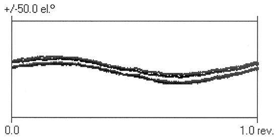
Image text: Dividing error of an incremental encoder.
For absolute encoders the term accuracy relates to the deviation from the absolute encoders optimal theoretical position. The unit used for accuracy of an absolute encoder is LSB, Least Significant Bit. On an absolute encoder with 13 bit singleturn resolution (213 = 8192 position) the accuracy is ±1LSB which implies that the maximal mechanical angle deviation is:
360° / 8192 = ±0.04°
Accuracy and calibration charts for each delivered encoder can be provided upon request.
2.5 Channel separation on incremental encoders
The specification of accuracy also includes the term channel separation, which is the distance between adjacent pulse edges of the S00 and S90 output signals. During final adjustments this is tuned to 90 el° and should lie within 90 ±25 el° for standard encoders. This means that the distance between adjacent pulse edges can vary between 65 el° and 115 el° for an approved encoder. Channel separation error is included in the dividing error.
The duty cycles of all incremental encoders are 180 el° or 1:1 unless stated otherwise.
Every delivered encoder is verified with respect to their accuracy, channel separation and duty cycle accomplished by monitoring that all pulse edges lies within approved limits. The measured values for maximum deviations from the encoder specifications are referred to the encoder’s serial number and collected in a database for statistical follow-up and future reference.
All accuracy data refer to measuring signals at an ambient temperature of 20°C, and with controlled subsequent electronics and transmission lines.
You may also be interested in:
Example of incremental encoders
Here you can see some examples of our most beloved incremental encoders.