3. Encoder interfaces: Incremental interfaces
3.1 TTL electronics/RS422
3.2 HTL and HCHTL electronics
3.1 TTL electronics/RS422
Incremental TTL-signals are transmitted as digital squarewave pulse trains S00 and S90, phase-shifted by 90 el°. The reference mark signal consists of one reference pulse denoted as Sref, which is gated with the incremental signals. As an option on TTL-encoders, the integrated electronics also produce inverse signals of S00 and S90 for noiseproof differential transmission. In this case the encoder signals comply with the RS422 standard.
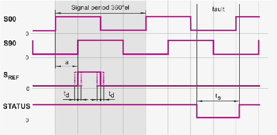
Image text: Output signals, TTL electronics.
| Interface | Square-wave TTL or RS422 (differential) |
| Incremental signals | S00, S90 (optional S00, S90) |
| Reference mark Pulse width Delay time |
Sref (optional Sref) 90 el° (other on request) td < 50 ns |
| STATUS (optional) Pulse width |
Improper function: Low Proper function: High ts > 20 µs |
| Signal level | Uh > 3 V with - Ih = 10 mA Ul < 0.4 V with Il = 10 mA |
| Permissible load | Z0 = 100 W Il < ±20 mA (per output) Cload < 1000 pF Outputs are short-circuit protected max. 1 min against 0V and +EV |
| Switching times (10% to 90%) |
t+/t- < 200 ns With 1 m cable and recommended input circuitry |
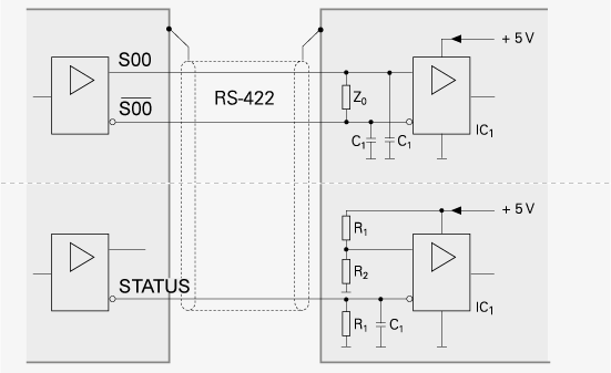
Image text: Recommended subsequent electronics, TTL / RS422.
The permissible cable length for transmission of the TTL square-wave signals to the subsequent electronics depends on the edge separation and whether differential (6 channels) or single-ended transmission is used. Note that the permissible cable length is calculated as long as the power supply can be ensured at the encoder. Make sure to compensate for voltage drop in the power supply lines.
3.2 HTL and HCHTL electronics
Leine Linde encoders with HTL interface incorporate electronics that digitize sinusoidal scanning signals. The incremental signals are transmitted as digital square-wave pulse trains S00 and S90, phase-shifted by 90 el°. The reference mark signal consists of one reference pulse Sref, which is gated with the incremental signals. In addition, the integrated electronics produce inverse signals of S00 and S90 for noise proof differential transmission. The fault-detection signal STATUS indicates fault conditions such as under voltage of the power supply or failure of the light source. It can be used for such purposes as machine shutoff during automated production.
To prevent counting error, the subsequent electronics should be designed to process as little as 90% of the edge separation a. See diagram below.
The permissible cable length for incremental encoders with HTL signals depends on the scanning frequency, the effective power supply and the operating temperature of the encoder.
Image text: Output signals, HTL / HCHTL electronics.
| Interface | HTL or HCHTL |
| Incremental signals | S00, S90 (optional S00, S90) |
| Reference mark Pulse width Delay time |
Sref (optional Sref) 90 el° (other on request) td < 50 ns |
| STATUS (optional) Pulse width |
Improper function: Low Proper function: High ts > 20 µs |
| Signal level (at 24V feed) |
Uh > 21 V with - Ih = 20 mA Ul < 2.8 V with Il = 20 mA |
| Permissible load | Z0 = ±40 mA Il < ±100 mA (per output) Cload < 10 nF Outputs are short-circuit protected max. 1 min against 0V and +EV |
| Switching times (10% to 90%) |
t+/t- < 200 ns With 1 m cable and recommended input circuitry |
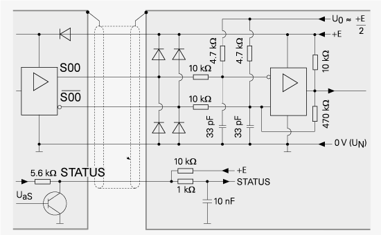
Image text: Recommended subsequent electronics, HTL.
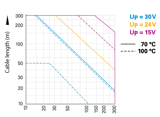
Image text: The graph shows the permissible cable length at various frequences for HTL encoders.
Example of incremental encoders
Here you can see some examples of our most beloved incremental encoders.